 *
*
Automated plant sample transfer systems and extractive continuous emission monitoring (CEM) technology has been around for decades but continues to suffer from issues that can cause operational maintenance & calibration problems and can result in costly plant shutdowns. So how can operators identify sources of problems and prevent future shutdowns?
Let's start with the common sample transfer system problems. Note the problem may be just a symptom of a deeper issue.
Common problems include:
- Low flow rates
- Loss of analytes or poor chromatography
- System leaks
- Sample condensation/phase loss
- Sample adsorption/retention
- Shift in operational results
Other very real problems include:
- Increase in spare parts usage
- Excessive labor costs
- Loss of data
- Disruption to hourly emission sampling
The symptoms can be be obvious but the cause of sampling and monitoring issues can be less visible.

Here are a few sources of potential sample transfer and CEMS performance issues:
Sampling related
- Probe damage or clogging cause by corrosion or fouling
- Adsorptive fittings, probe, and tubing
- Probe placement out of flow stream
- Condensation or cold spots in heat trace tubing
- Clogged or adsorptive filters
- Poor material selection resulting in corrosion
- Condensation or analyte phase change in sample transfer tubing caused by:
- Cold spot in heat trace tube
- Dips in installation flow path
- Moisture accumulation
Maintenance related
- Replacement of approved components with substandard components
- Contamination resulting from steam cleaning
- Cleaning with low grade low purity solvents
- Poor record keeping
Calibration related
- Use of expired or near expired cal gas
- Wrong cal gas concentration
- Filter adsorption
- Used regulators or off spec regulators not designed for calibration
CEM or instrument related
- Adsorption by instrument flowpath components
- Alarm failure
- Data loss
- Missed preventative maintenance
- Column or cell damage or contamination
The cost?
The end game of sampling processes is not the act of taking the sample but gathering reliable data and trends about the performance of the plant, system, or emissions monitored. The biggest cost of a poor performing CEM is the loss of reliable data. Data loss or corrupt data can lead to really nasty problems like a plant shutdown, poor product yield, or re certification of the monitoring system.
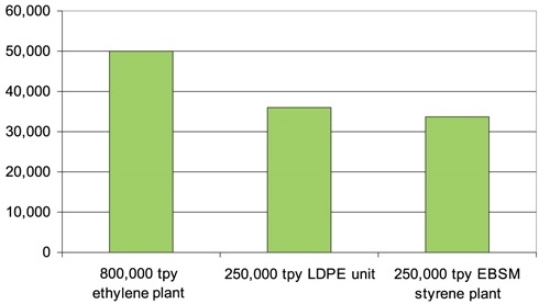
California studies have concluded the average cost for an unscheduled refinery shutdown in the state (resulting from an accident) averages $220 million. Even a one hour plant shutdown can be costly for petrochemical plants. Unplanned costs range from $30,000/hr up to $50,000/hr!
How to save money and reduce plant shutdowns? Selecting the right flow path material is key.
Barbara Marshik, PhD with MKS, presented at EPA Region 6 - 25th Annual Quality Assurance Conference on October 21st, 2015. She discussed Roberto Bosco's work on emissions testing using extractive FTIR. The presentation, entitled "Material and Process Conditions for Successful use of Extractive Sampling Techniques",** highlights emissions testing protocol and best practices for sample transfer & continuous emission monitoring (CEM) ratification by FTIR. The presentation discusses sampling issues common to analyzer and CEM systems and offers methods to resolve common problems.
The presentation reviews troubleshooting and calibration of CEMs and compares the effectiveness of materials commonly used in extraction and transport of reactive gases such as ammonia, HF, hydrochloric acid, nitrogen dioxide, and formaldehyde.

The test concludes that SilcoNert coated flow paths perform exceptionally well even in harsh environments found in stack probes. The test summary below highlights and compares stainless steel, SilcoNert® coated stainless steel, PTFE, and glass surfaces.* The SilcoNert coated surface performs well in most probe tubing and filtration applications.

SilcoNert® coated stainless steel probes add both inertness and limited corrosion resistance benefits, improving test quality and component durability. SilcoTek® offers other high durability inert coatings like Dursan® and Silcolloy® that can further improve durability while maintaining a non-retentive surface.

Sample lines, both heated and unheated, can be a major source of sample degradation. Design and installation issues can cause leaks, flow problems, condensation, and sample adsorption. Proper installation and appropriate heat trace temperature settings can correct leak, flow, and condensation issues. Unfortunately, appropriate heat trace temperatures may increase the likelihood of leaks or tube failure if the sample line is made of PTFE or other temperature limited material. SilcoNert coated stainless steel heat trace tubing offer both inertness and durability, making sample lines high temperature capable, and inert.*

SilcoNert was not tested in calibration applications. That is unfortunate because inert coatings can be applied to fritted filters, regulators, valves, fittings, and tubing; significantly improving calibration response for reactive compounds like H2S.

Coated flow paths may cost a few more dollars but the long term savings can vastly improve profits. Saving one hour of plant shutdown will pay for the cost of coating a flow path by orders of magnitude. SilcoTek is possibly the cheapest insurance policy around!

Use SilcoTek® inert coatings throughout the sampling flow path. SilcoTek coatings improve system durability while helping to prevent several common CEM problems.
Coat the entire sample flow path:*
*Image and data credit: "Material and Process Material and Process Conditions Conditions for Successful Use for Successful Use of Extractive of Extractive Sampling Techniques", (Marshik, Bosco, MKS, https://www.epa.gov/sites/production/files/2015-11/documents/c15-marshik-p2.pdf)
** (Marshik, Bosco, MKS, https://www.epa.gov/sites/production/files/2015-11/documents/c15-marshik-p2.pdf)


