We discuss chemical vapor deposition and how to maximize the benefits of a CVD coating.
|
In this blog post you will learn:
- How CVD (chemical vapor deposition) works.
- Characteristics of a CVD process
- Benefits and drawbacks of chemical vapor deposition.
- How to maximize the benefits of the CVD coating process
|
Chemical Vapor Deposition Benefits and Limitations
A CVD coating is a material applied to a surface by a method called chemical vapor deposition. Let's discuss how the coatings are made, coating benefits, limitations, and how to get the most out of your coating.
CVD coatings are prevalent throughout industry and can be found in many consumer products. They're known as being an environmentally friendly durable thin film surface. CVD products can be found in applications ranging from machine tools, wear components, analytical flow path components, instrumentation and many other areas demanding a high performance thin film. There are lots of thin films out there so what is it about the chemical deposition process that makes a superior coating for high performance precision applications?
About CVD Coatings: What is Chemical Vapor Deposition?
Chemical vapor deposition is a process that involves the reaction of a volatile precursor which is injected into a chamber (typically under vacuum). The chamber is heated to a reaction temperature that causes the precursor gas to react or break down into the desired coating and bond to the material surface. Over time the coating material builds on the surface and creates a coating throughout the exposed part's surface.
So for example if we wanted to bond silicon to a surface we may want to use a trichlorosilane (SiHCl3) precursor. When the trichlorosilane is heated in the coating chamber the decomposition and coating reaction may look like this.
SiHCl3 → Si + Cl2 + HCl
The silicon will bond to any exposed surfaces (both internal and external) while the chlorine and hydrochloric acid gas will be vented from the chamber and scrubbed according to appropriate regulatory requirements. Watch our coating video to see how CVD coatings are applied.
Want to learn more about our coating process? Go to our Coating Technology and Quality page.
Materials used in CVD coating systems range from silicon compounds to carbon, to fluorocarbons or organofluorine, and nitrides like titanium nitride. Some materials like silicon can be further enhanced by doping the surface (altering or adding an additional chemical) to functionalize the coating for a specific performance goal (as noted above).
Need help selecting the right CVD coating for your application? Try our online coating selector guide.

Chemical vapor deposition differs from other common coating application methods like physical vapor deposition (PVD). PVD involves vaporizing a coating material and spraying or condensing the vaporized material on the surface. Most common coating spray processes result in a line of sight application compared to chemical vapor deposition which is non line of sight. Comparing coated parts would look something like the graphic below.
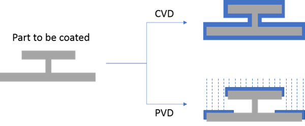
I like to think of PVD part coverage being something like snow covering my deck furniture. Under my table there's little to no snow while there's lots of snow on top of the table. With PVD, surfaces must be exposed to the application vapor; shielded areas won't be coated (like under my table).
Chemical vapor deposition coatings can be theoretically applied to any area the coating gas can get into. Process control is another factor in utilizing CVD coating processes. The deposition process allows us to build a coating layer (in our case corrosion resistant or inert silicon) on the surface one Angstrom (0.1 nanometer) at a time. In theory we should be able to specify a coating to the nanometer, so why do CVD coatings have a thickness range? In practice, variation and process limitations result in specifying a range of coating thickness. But that thickness range can still be quite small.
Characteristics of a CVD coating process
- Applied at elevated temperature to facilitate reaction.
- Typically applied under vacuum.
- Contaminants must be removed from the part surface before coating application.
- Process may limit the base materials that can be coated. I.e. temperature limitations or reactivity limitations.
- Process may limit the ability to mask specific target areas.
- Unlike most PVD (physical vapor deposition) processes, the CVD Process is not limited to line-of-site application. Coating gas will coat all areas of a part including threads, blind holes, and interior surface.
- Film thickness is limited due to coating stress.
- Coating is bonded to the surface during the reaction which creates a superior adhesion when compared to typical PVD or low temperature applied spray coatings.

Coating Benefits
- Can be applied to a wide variety of base materials including ceramics, glass, metals and metal alloys.
- Can coat precision surfaces and intricate surfaces including seal areas and internal surfaces.
- Can withstand exposure to low and high temperature and extreme temperature variation.
- A durable coating to substrate bond means the coating remains bonded in high stress environments, even when the substrate surface flexes or bends.
- Precursor gas can be optimized for chemical inertness, high lubricity, corrosion resistance, fouling resistance, high purity, or wear resistance.
Have a question about a coating application? Get a free technical consultation with one of our coating experts.

Coating Drawbacks
- Typically applied at higher temperatures (depending on the precursor).
- Difficult to mask surface. Usually an all or nothing coating.
- Size limited to reaction chamber capacity.
- Parts must be broken down into individual components
- Not an "on site" process, parts must be shipped to a coating center.
Getting the Most Out of the Coating Process
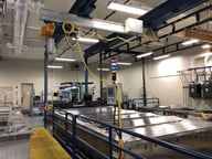
Fixturing
Making something to hold something else has been around as long as people have walked the planet. Think of early tools and spears. A stick was nothing but a fixture to hold the tool or the deadly end of a spear tip. From that beginning people have been working on novel ways to hold things in order to make life or products better. That's exactly what SilcoTek® does with their fixtures. We use them to improve our CVD process and the performance of your products and to eliminate factors that can lead to coating variation. In fact we have an Engineering team dedicated to the design and development of processes, and specifically fixtures, to be used in our process.
To learn more about our CVD coating process go to our process technology page. Or click on the box below to subscribe to our coating science blog and emails.

Where are fixtures used at SilcoTek?
That all depends on the customer part, quantity of the parts and frequency of use. For a customer shipping parts regularly to us for coating we may agree to a shipping container that holds the part or parts safely in place during transportation. We may develop a fixture to hold the parts during our surface preparation process and we may design a fixture that protects and supports our part in the coating reactor. Unfortunately there's no "one size fits all approach" to fixture design.
We design and use part holding systems to benefit overall part quality. Benefits include:
- Preventing part damage
- Assuring a consistent coating throughout the part
- Improve the quality of surface preparation
- Prevent damage during shipping or transportation
- Improve coating efficiency
Minimize Sources of Process Variation
The table below summarizes the range of coating thickness for each coating. So why the difference in thickness? Well there are lots of contributing factors that add up to variation in the thickness of our coatings.
To to our Coating Specifications and Properties page to get complete coating specs.
Here are a few contributing factors that add to variation in the coating process and how you can maximize the benefit of the process.
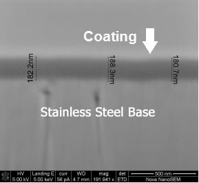
1. Part surface
Is the part electropolished to a mirror finish with little surface roughness (5 ra for example?) or is the part cast with an extremely rough surface? Our coating process will coat the entire part but may preferentially coat some areas of a rough surface like a peak. We're not talking about a large amount of variation but the surface roughness can be a contributor. The SEM image below is a good example. You can see some changes in the part surface (light gray) and the impact on the overall coating thickness. Over the small sample area of the surface you can see 8nm in thickness variation.
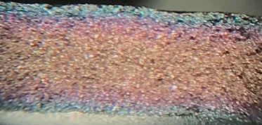
2. Part Configuration
As noted, our process will coat the interior of a part as well as the exterior. Here the available coating volume can play a part in coating thickness. A small confined area, like the interior bore of a needle, will tend to have slightly less coating available to bond to the surface. We have a few tricks that we use to minimize the effect but in some part configurations the coating thickness can change, especially in blind holes or extremely narrow bores or within fritted metal filters like the photo below. The section of the fritted filter shows a band of color. This indicates variation in coating thickness from interior to the exterior of the filter surface.
3. Base Material and Surface Condition
This is an area where the customer can maximize the coating quality. We coat mostly stainless steel alloys but we can also coat glass, ceramics and more exotic alloys like titanium. The base material can affect the coating rate under certain conditions and add to variation. Our process can minimize this problem but if the base material surface is oxidized, heat stained, etched, buffed, or scratched the coating thickness can vary in those areas.
Also if the part has been exposed to lubricants or process chemicals, let us know when you place the order. Knowledge of chemical exposure will help our technicians to properly prepare the part surface for optimal coating.
4. Coating Reaction Rate
The ideal chemical vapor deposition strikes a balance between process time, cost and coating thickness variation. SilcoTek's process has optimized cost, time and value for the customer without impacting coating performance. SilcoTek has spent thousands of hours evaluating and optimizing coating performance for each industry application.
Optimization involves trade-offs between process and performance. Those trade-offs happen all the time in manufacturing shops, surface finish operations and in virtually all products made today. To maximize the benefit of an optimized coating process, plan for a coating lead time of 5 to 10 business days. That will allow our process technicians to provide the highest performing coating for your application.
Stay in touch with the latest in coating technology. Subscribe to our blog or follow us on LinkedIn.