
Customers may ask for a hard coating, but often what they're really asking for is a wear resistant coating. What's the difference and which is better? That depends.
Wear Resistance vs. Hardness Which is Better?
|
In this blog post you will learn:
- The difference between wear resistance and hardness when comparing coating performance.
- How hardness is measured and calculated.
- How wear resistance is measured and calculated.
- When to specify wear resistance vs. hardness when selecting a coating.
In a follow-on blog we'll discuss comparative results of wear and hardness tests.
|
Background
Hardness refers to a material's resistance to permanent deformation and applies to a material's ability to resist indentation, scratching, cutting or bending. Wear resistance refers to a material's ability to resist material loss by some mechanical action. A material can be wear resistant and tough but not particularly hard, and a hard material can be wear resistant but not particularly tough. Let's explain the difference a bit further.
Toughness is a material's ability to absorb energy and deform (elastically and plastically) without fracturing. Think of car tires for example. Tires are not particularly hard. You can stick your fingernail in some tires, but the tire bounces right back even after extreme deformation (elastic deformation). Even if a tire is permanently deformed (plastic deformation) it rarely tears or breaks. Yet those tires take a really long time to wear out despite rolling on much harder surfaces like concrete. (Yes a fast car doing a burnout can go through a tire quickly but you get my point.) They also withstand extreme temperatures and shock. Tires are tough, they deform, can absorb a lot of energy before failure and are wear resistant but they are not very hard.
Want to learn more about the properties and benefits of SilcoTek coatings? Get our introductory e-book, SilcoTek 101.

A hard material, think of glass for example, will have a very high resistance to deformation but can be highly brittle, susceptible to shock, or can be damaged when exposed to high temperature gradients. Glass is hard and wear resistant but not "tough". Some hard materials, like carbide and nitride materials, are better at resisting stress and shock than others. So simply asking for a hard material may not be the most appropriate criteria to base your material selection on. You may end up getting glass when what you really want is rubber.
So is it better to have a super hard coating or a wear resistant "tough" coating? That depends a lot on the application.
We tested our coatings for both hardness and wear resistance. In this blog we'll discuss the details of the tests and in part 2 of this blog we'll discuss test results and what is all means for coating selection.
Testing Methods
Two of our most popular coatings, Silcolloy® and Dursan® , were submitted to Penn State University’s Materials Characterization Lab for nanoindentation testing, to obtain the coating hardness and elastic modulus properties. A total of six 316 stainless steel (SS) sample coupons were analyzed, including two for each coating and two uncoated as baseline reference. The coupons all have a mechanically mirror-polished side and a standard machine-finished side. The polished side is used for the nanoindentation test.
For the wear testing, a pin-on-disc tribometer (TRB) was used to evaluate Dursan coated stainless steel and oxidized stainless steel coupons. Testing was conducted in accordance with ASTM G133.
Learn how SilcoTek® can solve your toughest material problems.

Hardness Testing Background
Indentation hardness tests are used in mechanical engineering to quantify the resistance of a material to plastic deformation (plastic deformation is the permanent change of a material's shape due to the application of mechanical stress, think of what happens when you hit a piece of wood with a hammer). Indentation hardness tests are usually carried out by touching the material of interest whose mechanical properties are unknown with another material whose properties are known. For example, the original Mohs’ hardness scale defines diamond as the maximum value of 10 on the scale, and material A is ranked harder than material B if A is able to leave a permanent scratch in B. Later methods such as Brinell, Knoop, Vickers, and Rockwell applied various refinements, but all follow the same essential idea.1 Depending on the length scale of the penetration, indentation hardness tests can be divided into three classes: macro, micro and nanoindentation, where the penetration length is measured in millimeters, micrometers, and nanometers, respectively.
In macro and microindentation tests, the area of contact between the indenter and the specimen is calculated from direct measurements of the dimensions of the residual impression left in the specimen surface upon the removal of load. However, this size becomes too small to be conveniently measured directly in a nanoindentation test. Instead, only the depth of penetration into the specimen surface is measured in a nanoindentation test. This value is then used together with the known geometry of the indenter to calculate the contact area indirectly.1

Hardness Experimental:
Samples were tested using a Bruker Hysitron TI-900 nanoindenter with a standard Berkovich tip made of diamond. The Berkovich indenter is a three-sided pyramid with a half angle of 65.3°, measured from the indentation vertical axis to one of the pyramid flats, as shown in Figure 1.2 The shape of the indentation left by a Berkovich tip is also shown in Figure 1. In order to exclude substrate interference, the indentation depth was controlled to be no more than 10% of the coating thickness. The coating thicknesses for the six coated samples varied between 700-900 nm, so test indents were performed first to determine the corresponding load value for each sample type to reach about 70 nm of indentation depth (including the uncoated control samples to be consistent). Each sample was indented on the polished side in 2 areas near the center, in a 5x5 XPM load function (a matrix that takes 25 individual measurements), giving 50 data points per sample, and a total of 100 data points per coating type including the bare stainless-steel metal.
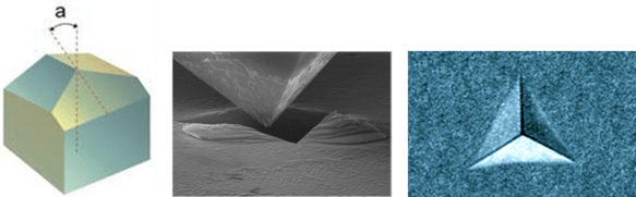
Figure 1: A Berkovich tip with “a” denoting the half angle,2 and the indentation shape it leaves on the surface of the testing specimen3,4
In a nanoindentation experiment, the indenter will penetrate the sample surface, producing both elastic (i.e. reversible) and plastic (i.e. permanent) deformation, until it reaches a predetermined maximum load, during which the displacement (h) and the load (L) are continuously monitored with high precision. During the indenter withdrawal, the unloading displacement continues to be monitored until zero load is reached and a final or residual penetration depth is measured.
Figure 2 shows a typical stress-strain curve, where stress is defined as the indentation force per unit area and strain the relative deformation (i.e. the change in dimension divided by the original dimension). The relationship between stress and strain is linear (i.e. elastic) up until the yield point, beyond which plastic deformation starts to occur.
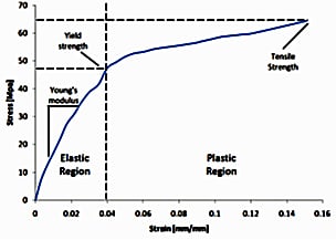
Figure 2: A typical stress-strain curve that shows the elastic vs. plastic regions of the deformation and how Young’ modulus is defined5
The slope of the linear part of the stress-strain curve (i.e. stress/strain) is called Young’s modulus, also known as the modulus of elasticity.1 It measures the ability of a material to resist elastic deformation in the direction that is under a tension or compression force. A stiff material like diamond has a high Young’s modulus, requires a very high load to elastically deform it, and changes its shape only slightly under an elastic load. A flexible material like rubber, on the other hand, has a low Young’s modulus and requires very little elastic force to change its shape considerably. A flexible material can be a tough (or strong) material at the same time, which means although it only requires a small load to elastically deform it, it requires a lot of energy to break it. Like those car tires we mentioned.
Nanoindentation Testing
In nanoindentation, the hardness of the testing specimen is defined as peak load / contact area, where the contact area (Apml) is the projected area of contact at the maximum load, as illustrated in Figure 3 below. This area can be calculated from the load-unload curve using an analytical model developed by Oliver and Pharr, without the need to directly measure the area with a microscope.6
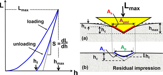
Figure 3: left - The load (L) vs. displacement (h) curve during the load-unload stage of a nanoindentation test, where hf is the final residual penetration depth when a zero load is reached during unloading. The slope of the upper portion of the unloading curve can be used to determine Young’s modulus; right (a) specimen deformation at the maximum applied load Lmax and (b) residual plastic deformation after complete unloading6
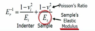
A “reduced modulus” or “combined modulus’ is reported from this test because the analysis took into consideration that both the testing specimen and the diamond indenter experience elastic deformation during the measurement. The testing sample’s elastic modulus Es (i.e. Young’s modulus) can be calculated from the reduced modulus Er using the equation below, given that the elastic modulus for the indenter and the Poisson’s ratios for both the indenter and the sample are known.1
Now that we've outlined how hardness testing is done, let's discuss wear resistance testing next.
Wear Resistance
Pin-on-disc measurement involves engaging an indenter or pin (usually flat or sphere shaped) on to a test sample. The engagement mechanism applies a precise force to the indenter as the test sample is rotated. The resulting friction forces are measured using a strain gage sensor. Wear coefficients for the pin and sample are calculated based on material lost during the test. Pin-on-disc can help determine a coating's wear resistance and also give an indication of the surface's coefficient of friction, lubricity, and adhesion properties. A low coefficient of friction surface with high lubricity will enable the pin to roll more easily on the surface which would reduce material loss and improve wear resistance. Conversely a coating with poor adhesion would be stressed by the pin, resulting in coating bond failure and coating loss. This would indicate poor wear resistance, even if the coating were hard.
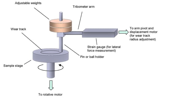 Figure 4: Typical pin-on-disc test apparatus.
Test Conditions
Testing was conducted in accordance with ASTM G133 by an independent lab, Nanovea. According to the Nanovea laboratory material test report: "The instrument base is first leveled in the horizontal position by screwing or unscrewing the adjustable rubber pads at each corner. A ball-holder containing a 3 or 6 mm diameter ball is held in the load arm and placed at a height that allow the tribometer arm to be leveled horizontally when resting on the sample to ensure that normal load will be applied vertically.
The arm is then balanced with counter weights to ensure that the arm and ball holder initially
apply no force on the sample surface. Finally, weights corresponding to the load required for the test are finely placed on the arm over the ball holder. Through software, the test is then launched and the test is performed at a specified speed for a specified duration, and the frictional force is recorded over time."
The pin-on-disc test will not provide an absolute hardness test but may offer additional insights into the ability of a coating to withstand challenging wear conditions.
So what's better a hard coating or a wear resistant coating?
That depends on the application. SilcoTek’s CVD coatings are generally lower in hardness and modulus values, meaning they are softer and less stiff, than the commonly used hard engineering coatings such as DLC (diamond-like carbon) or titanium-based coatings. Those coatings are usually used in mechanically demanding applications such as metal cutting, tooling, automotive and aerospace where they can reduce abrasive wear and improve lifetime of the components.
In other applications a hard coating may be more brittle and susceptible to shock but may have greater abrasion resistance; while a "tougher" material may be able to withstand varying wear, environmental, shock conditions or sliding applications but abrasion resistance may be lacking.
On one hand, high hardness and Young’s modulus are recognized and desirable characteristics for coatings used in mechanically demanding applications. On the other hand, we learned from this review that hardness and Young’s modulus alone do not translate to better wear-resistance, especially when comparing coatings or surface treatments. Other factors such as surface lubricity, coating adhesion and surface coefficient of friction also play important roles. In some applications, a soft but flexible coating material like rubber may fit the needs better than a hard but brittle material like glass.
In our next blog installment, we'll discuss test results that bring real data to the idea that hardness and wear resistance are not interchangeable terms and summarize what the data means.
Have a question about our coatings? Go to our FAQ page. Interested in keeping up with the latest in high purity CVD coatings? Subscribe to our blog.
References:
- Fischer-Cripps, A. C. “Nanoindentation” 3rd edition, 2011.
- https://en.wikipedia.org/wiki/Berkovich_tip
- https://www.bruker.com/products/surface-and-dimensional-analysis/nanomechanical-test-instruments/nanomechanical-upgrade-options/test-probes.html
- https://www.nanoscience.com/products/nanoindenters/
- Hess, A. E. “Integration of process-incompatible materials for microfabricated polymer-based neural interfaces” Ph.D. thesis, Case Western Reserve University 2011
- Broitman, E. “Indentation hardness measurements at macro-, micro-, and nanoscale: a critical overview” Tribol. Lett. 2017, 65:23
- https://www.azom.com/properties.aspx?ArticleID=863
- Kuschnereit, R. et al. “Mechanical and elastic properties of amorphous hydrogenated silicon films studied by broadband surface acoustic wave spectroscopy” Appl. Phys. A 1995, 61, 269.
- Guo, S. et al. “Internal stress, thermal expansion coefficient and bi-elastic modulus of photochemically vapor deposited hydrogenated amorphous silicon films” Thin Solid Films 1992, 219, 135.
- Li, H. et al. “Determining the elastic modulus and hardness of an ultra-thin film on a substrate using nanoindentation” J. Mater. Res. 2009, 24 (3), 1114.
- Gan, Z. et al. “Material structure and mechanical properties of silicon nitride and silicon oxynitride thin films deposited by plasma enhanced chemical vapor deposition” Surfaces 2018, 1, 59.
- https://www.silcotek.com/blog/wear-resistant-cvd-coating-tests-put-dursan-on-top
- Wiatrowski, A. et al. “Comparison of the physicochemical properties of TiO2 thin films obtained by magnetron sputtering with continuous and pulsed gas flow” Coatings 2018, 8, 412.
- Savvides, N. et al. “Hardness and elastic modulus of diamond and diamond-like carbon films” Thin Solid Films 1993, 228, 289.
- https://www.entegris.com/shop/en/USD/Products/Specialty-Materials/Coatings/Plasma-Enhanced-Chemical-Vapor-Deposition-%28PECVD%29-Coatings/c/plasmaenhancedchemicalvapordepositionpecvdcoatings
- Wu, S. et al. “Hardness and elastic modulus of titanium nitride coatings prepared by PIRAC method” Surface Review and Letters 2018, 25 (4), 1850040.
- Fieandt, L. V. “Cutting edge titianum-based CVD hard coatings” Ph. D. thesis, Uppsala University 2018.

