Chemical vapor deposition (CVD) reaches surfaces that are difficult or impossible to coat with methods that require a direct line of sight. SilcoTek’s CVD process seamlessly coats parts with internal passages, narrow bores, and other intricate features. But the ability to reach a surface is only one part of a successful coating project. The material, surface condition, assembly, and dimensions of a component all affect how it can be prepared and processed.
A part with a complex shape is not automatically unsuitable for coating; in fact, these are great use cases for SilcoTek’s unique coating application process. However, complex part designs gives us more to evaluate. Understanding these factors early allows us to provide the optimal process to get the best coating on the surfaces of your parts that are most critical to success in their end use.
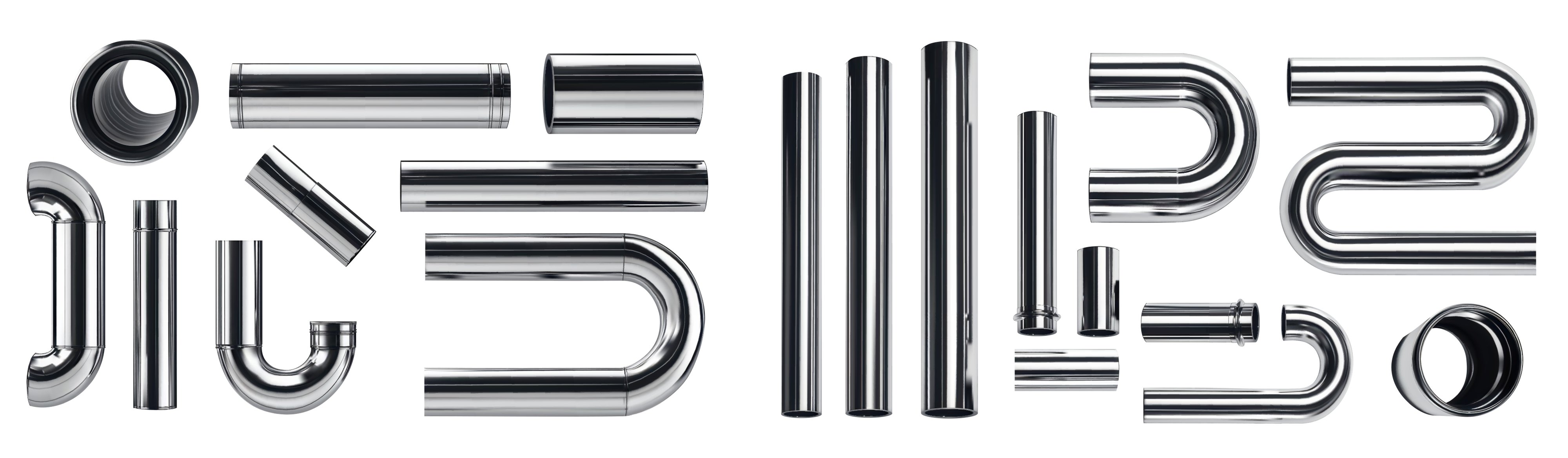
Narrow Passages and Blind Holes
Internal surfaces are often the most important surfaces to coat. In an analytical flow path, for example, the sample of interest usually contacts an injection port or other sample introduction component, the inside of tubing, the internals of valves and fittings, and sometimes a filter before it ever reaches the detector.
SilcoTek can coat small bores, sample needles, blind holes, and other intricate features because our process gases enter openings that a line-of-sight coating method can't reach. However, coating thickness can vary within confined areas. Blind holes, extremely narrow bores, and fritted or sintered metal filters are examples of part configurations that can affect thickness.
If an internal surface is critical to the part’s performance, identify it during the design review. A drawing showing the dimensions and location of the critical surface gives us a clearer picture of what the coating needs to accomplish.
Tubing Length and Configuration
Tubing brings its own design questions. Is it straight, coiled, or already bent? What is its internal diameter? Does the application require coating on the inside only, or on both the inside and outside?
Those details help determine how SilcoTek processes the tubing. As shown on our tubing guide, straight lengths are always coated internally and externally through one process, while coiled tubing is processed internally-only through another. The guide lists an 80 inch maximum for straight tubing in its internal and external process. For coils, the tubing diameter and overall coil dimensions affect what can be accommodated and how much tubing can be coated.
For long or especially narrow tubing, involve SilcoTek before committing to a final configuration, if possible. Providing the internal diameter, length, outside diameter, and planned coil or bend dimensions allows the team to review the intended flow path.
.jpg?width=469&height=522&name=Max%20coil%20length%20table%20(003).jpg)
Assemblies That Need to Come Apart
A valve or regulator may look like a single part, but it often contain seals, O-rings, plastics, and other components that are incompatible with coating conditions. Assembly also makes internal surfaces harder to clean, expose to coating gases, and inspect afterward.
Surfaces That Need Special Handling
Every part must be supported while it is cleaned and coated - sadly, we haven’t figured out how to levitate parts (yet)! SilcoTek uses fixtures or other holding equipment that we design and manufacture in-house to position parts during processing. The right approach depends on the part’s size, shape, quantity, and sensitive surfaces.
A support point can leave a slight difference in coating thickness or color where it contacts the part. That makes it useful to identify polished, easily damaged, or critical surfaces in advance. SilcoTek then considers those areas when determining how to hold the component.
This is particularly relevant for a part whose critical surface is also the most convenient place to support it. A drawing that marks the allowable support areas will make that conversation more productive.
Surface Condition, Welds, and Joined Materials
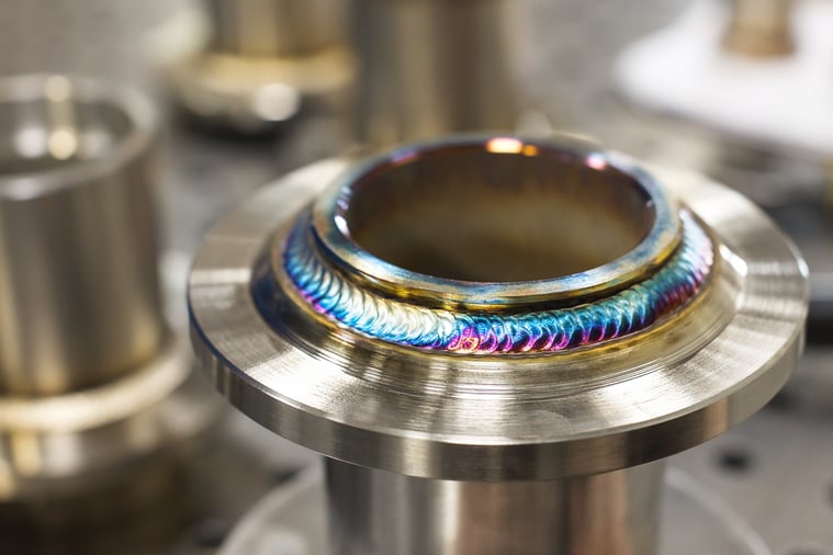
CVD coatings conform to the surface underneath them. They do not remove pits, scratches, corrosion, or rough welds. Oxidation, heat staining, etching, buffing, and scratches can contribute to variation in coating appearance.
Joined parts warrant a closer look. The welding, brazing, or soldering method and the materials used at the joint can affect process compatibility. SilcoTek’s pre-coating guide lists joining methods we can accommodate. Read the entire coating success and care guide below.
The order of manufacturing steps matters, too. Please also note that welding after coating removes the coating around the heat affected zone. If welding is part of the design, discuss when it will occur rather than assuming the coated surface will remain intact through later fabrication.
Machining and Cleaning History
Two parts made from the same material and to the same drawing may arrive with very different surface conditions. Cutting fluids, cleaning products, pickling, and other manufacturing steps can leave residues that affect coating adhesion.
We have published examples of coating problems traced to changes in cutting fluid and cleaning practices. In those cases, identifying the upstream process helped the customer and SilcoTek resolve the issue.
If a machine shop, material supplier, or cleaning process changes, tell SilcoTek even if the finished part looks the same. That information may be useful when reviewing how the surface should be prepared for coating.
Is the Base Material Compatible?
Part geometry is only one consideration. The substrate and any joined or attached materials must also be suitable for SilcoTek’s process and for the component’s eventual operating conditions. SilcoTek coats a variety of materials, but compatibility should be evaluated for the specific part and application. Check to see if your materials are on our material compatibility guide below.
This is especially useful to address while a new component is still being designed. Sharing the exact material specification gives SilcoTek an opportunity to discuss compatibility before parts are manufactured.
What to Share With SilcoTek
A helpful design review starts with a drawing or clear photos and a description of what the part does. Include its material, dimensions, and intended operating conditions. Then point out:
- The internal and external surfaces that are most critical for receiving coating
- Narrow passages, blind holes, tubing lengths, coils, or bends
- Welds, brazed joints, and materials used in an assembly
- Polished or sensitive areas, plus any acceptable support points
- Previous chemical exposure, cleaning, or surface treatments
Our team uses all those details to evaluate the part and discuss the coating approach. The sooner critical surfaces and manufacturing constraints are identified, the easier it is to address them before the design is finalized or the parts are shipped.
Have a component with an unusual geometry or a critical internal surface? Contact Us to review the part and its application.
Follow Us on Social Media!