We discuss the best practices for sampling hydrogen impurities from experts in the field. Let's review the recommendations and results.
Sampling for Hydrogen Impurities Best Practices
A paper from the European Metrology Program for Innovation and Research (EMPIR) and the European Association of National Metrology Institutes (EURAMET) discusses best practices for sampling hydrogen contaminants and tests various surfaces for effectiveness in supporting high quality hydrogen sampling results. We weigh in on best practices for sampling for hydrogen impurities.
|
In this blog post you will learn:
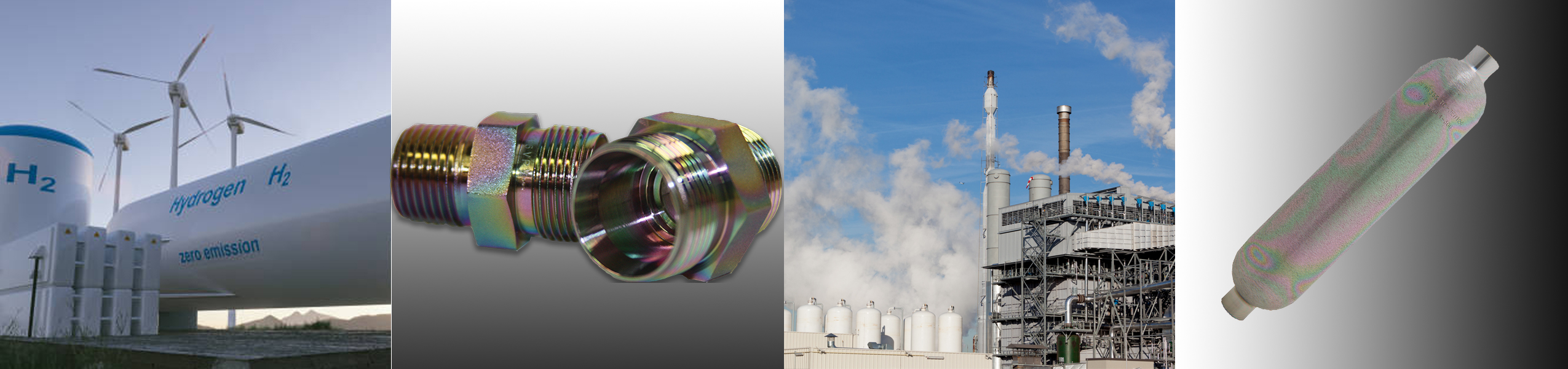
- Common contaminants found in hydrogen, a key fuel used to replace hydrocarbon fuels and reduce greenhouse gas emissions.
- Contaminants that can adsorb into sample flow paths and disrupt test quality.
- What surface materials/coatings improve sample results.
|
Hydrogen Impurities Background
In a previous blog we discussed the coming hydrogen economy and how coatings benefit hydrogen production and use. In that blog we discussed the various impurities that can affect hydrogen quality.
Table 1 below highlights contaminants that can affect the performance of hydrogen powered systems, either in the production of hydrogen, the delivery of hydrogen, or in the efficient operation of the power system (internal combustion engines or fuel cell systems).
Some contaminants can reduce the efficiency of hydrogen production or damage catalysts which can result in catalyst poisoning and premature system failure. Contaminants can also damage hydrogen transport systems. For example water can freeze valves, regulators or filters while particulates can damage or interfere with gaskets and seal areas or clog filters.

Still other contaminants, like N2, NOx or CO2, may not directly damage the fuel delivery system or damage the fuel cell, but can reduce the overall energy density of the fuel. This can result in poor performance in fuel cells or internal combustion engines. An increase in air emissions (NOx, SOx, etc.) may also result from contamination in the fuel stream.
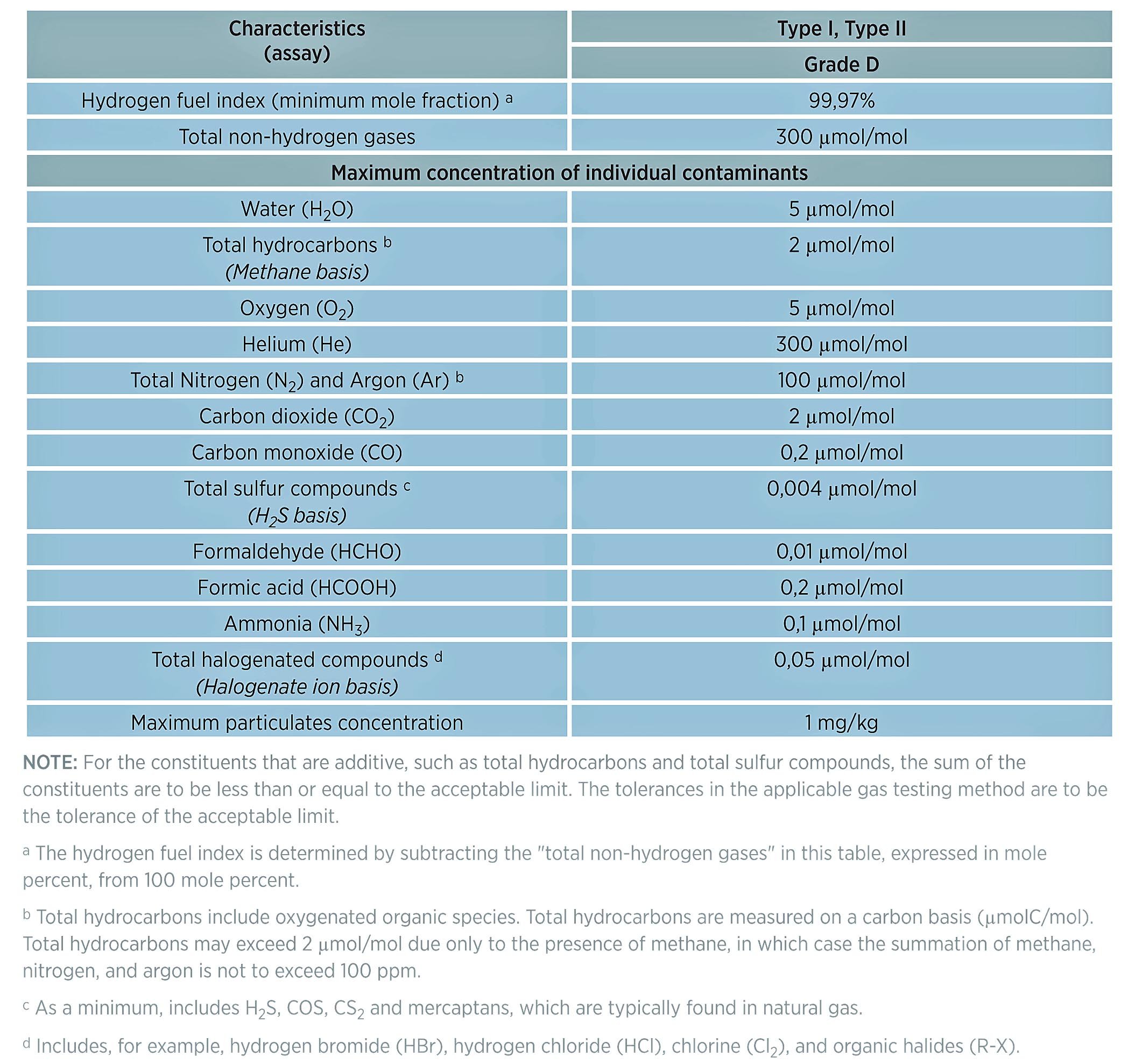
Table 1: Directory of limiting characteristics (maximum allowable limits of contaminants) from ISO FDIS 14687-2. ( "Hydrogen Fuel Quality Specifications for Polymer Electrolyte Fuel Cells in Road Vehicles", US Department of Energy, 2016 )
According to a study by the US Department of Energy, the contaminants that pose the greatest danger to the performance of hydrogen production, delivery, and power systems like fuel cells or internal combustion (IC) engines include:
- Carbon monoxide (CO) - CO can absorb onto the fuel cell surface and prevents hydrogen production.
- Sulfur and sulfur species like hydrogen sulfide (H2S) - Sulfurs will contaminate the fuel cell catalyst and hydrogen production catalysts. Even trace sulfur contamination can quickly and irreversibly damage catalysts, causing poor performance and eventual premature catalyst replacement.
- Ammonia (NH3) - Ammonia can can also poison catalysts and impede hydrogen production. Levels of ammonia as low as 2 ppm have been shown to result in degradation of hydrogen production.
- Inert gases like nitrogen (N2) or oxides of nitrogen (NOx), or carbon dioxide (CO2) - inert gases do not damage catalysts or other system flow path components but they will reduce the overall energy density of the gas stream, reducing the performance of the downstream equipment like fuel cells or internal combustion engines using hydrogen as a fuel.
- Methane CH4 - Methane can also dilute the hydrogen gas stream. Methane contamination in production processes can reduce the overall hydrogen production efficiency.
- Water - Water can freeze in process and transport flow paths, inhibiting operation or damaging valves, regulators, orifices, or filters.
- Aromatic hydrocarbons - Aromatic hydrocarbons, like benzene BTEX (the name for benzene, toluene, ethylbenzene, and xylene contaminants) can absorb onto the catalyst surface and block or inhibit hydrocarbon production.
- Fine Particulates (below 10 microns) - particulates can damage flow path seals and blind filters.
Some of the contaminants listed by the US Department of Energy and highlighted in ISO14687 Grade D are also highly reactive to flow path surfaces.** Those materials include:
- Hydrogen Sulfide (H2S)
- Ammonia
- Halogenated compounds (like fluorine, chlorine, or bromine)
- Formic acid
- Carbon monoxide
- Formaldehyde
The combined effects of contaminants in hydrogen production and use can result in an increase in production cost, impact reliability and performance of catalysts, can increase air emissions, and can potentially lead to safety and reliability issues in transportation systems. All of these negative effects can inhibit the expansion of hydrogen use in the greater economy and limit hydrogen's potential as a contributor to achieving carbon neutrality in energy use and production.
It's important to properly specify the flow path material and storage containment materials in order to minimize adsorption and assure the entire hydrogen sample (contaminants included) reaches the analyzer and detector.
Sampling Best Practices
Before sampling hydrogen, or any substance for that matter, best practices outlined by industry standards should be followed. Best practices include:
- Assure material compatibility with the system, environment, test conditions, and analyte. This includes accounting for system pressure, corrosion resistance, temperature exposure, physical use and damage; as well as analyte adsorption and reactivity.
- Be sure all flow path components are not damaged and perform to specification.
- Flow path surfaces should be cleaned in accordance with industry standards. Cleaning solvents should be tested or certified that no trace contaminants are left on the flow path surface after the cleaning process.
- Flow paths and analytical equipment should be tested with a control sample to assure the system is performing to standard.
The EURAMET paper discusses additional factors to consider. The paper states:
"While selecting a vessel for sampling hydrogen, several parameters must be considered:
- The vessels must be cleaned and evacuated before sampling
- No loss of impurities shall occur during transportation (Timeline: 2-4 weeks maybe even longer if e.g. transported to Europe from USA or Asia)
- Sampling hydrogen may imply the presence of several species at the same time; it must be ensured that the vessel(s) is/are suitable for all impurities
- The vessels need to be approved for transportation
- The vessels need to be compatible with available hydrogen sampling devices developed to take samples at Hydrogen Refueling Stations (HRSs)
Decision about the suitability of a specific vessel for hydrogen sampling must consider all these parameters. The most restrictive parameter is the compatibility of the vessels with the sampling device. Currently, mainly three sampling devices are in use: the European variant for parallel sampling according to ISO19880-1, annex I [2] using a Qualitizer and a 10 l cylinder, the US variant for series sampling according to ASTM D7606:1 [3] and the Japanese variant. All the sampling devices require a gas cylinder as sampling vessel."
Testing Data
Trace Sulfur and Sulfur Compound Detection
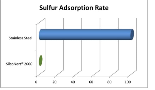
Stainless steel is a material commonly used in hydrogen production and transport systems. Unfortunately sulfur (one of those natural gas contaminants) is readily adsorbed onto stainless steel flow path surfaces. This makes detecting and managing sulfur poisoning more challenging. Sulfur detection is generally a manageable problem when testing at higher concentrations, but at trace levels, detection is much more difficult.
Unfortunately, hydrogen catalysts are vulnerable to trace level sulfur poisoning. The damage from sulfur can add up quickly, resulting in reduced efficiency and shorter catalyst life. Both very expensive results. This makes testing for even trace level sulfur essential to cost efficient hydrogen production and use.

When testing for sulfur using materials like stainless steel, metal alloys, or even glass, the sulfur is adsorbed in the flow path and never reaches the sulfur detector. This results in reduced sulfur response at the detector and a false negative test; when in fact the feedstock stream may be poisoning the catalyst.
The flow test plot below demonstrates how various surfaces perform in trace sulfur analysis. The coated surfaces provide fast response and result in a higher detection signal when compared to uncoated stainless steel.
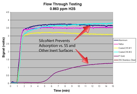
SilcoNert® radically improves sulfur response over uncoated stainless steel in analytical systems. This helps to maintain consistent and reliable detection, keeping hydrogen processing and fuel cell catalysts safe from poisoning.
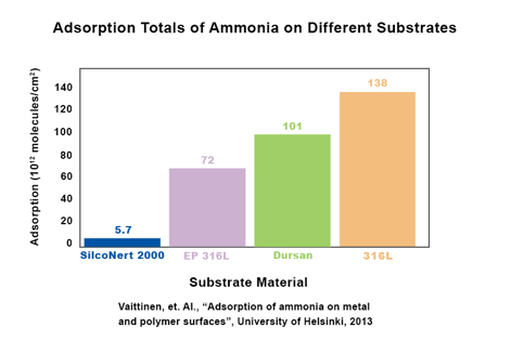
Ammonia Detection
Like sulfur contamination detection, improved ammonia detection can also contribute to preventing damage to catalysts. SilcoNert improves test reliability and lowers the detection limit of ammonia, helping to detect ammonia contamination before catalysts are damaged.
A University of Helsinki study found that SilcoNert improves the trace detection of ammonia by 95% when compared to uncoated 316L stainless steel. Improved detection will enable refiners and users to better manage hydrogen fuel quality and maintain high efficiency in production and use.
The EURAMET study tested various sample cylinders over a period of 6 months. Test conditions for the SilcoNert® and Dursan® sample cylinders were (as quoted from the study):
"The suitability of a Dursan, a Sulifnert and an untreated stainless-steel sampling vessel (1
litre) was tested with a hydrogen gas mixture containing around 40 ppb H2S and 110 ppb CO from Test 2. Tests were performed 6 months after the preparation of the mixture. These tests were carried out at RISE."
The comparative results showed that SilcoNert® (called Sulfinert® in the study) cylinders performed well in the study, with good H2S stability throughout the test period at 24 ppb. Dursan did not perform well in the study with loss after a day. It's unclear why Dursan underperformed under the test conditions.

Carbon monoxide remained stable in SilcoNert, Dursan, and untreated cylinders.
For CO, the results show that the amount fraction of CO remains stable in coated and uncoated cylinders.
To learn more about how our coatings benefit analytical performance, go to our website, contact our Technical Service Team, or follow us on LinkedIn.

** Karine Arrhenius; Haleh Bohlén; Sam Bartlett; Heleen Meuzelaar; Stefan Persijn;Janneke van Wijk: Metrology for Hydrogen Vehicles Report, "Good practice on the suitability
of vessels and gas cylinders for sampling hydrogen as required by ISO14687";
https://www.sintef.no/globalassets/projectweb/metrohyve-2/good-practice_suitability-of-vessels-and-gas-cylinders-for-sampling-hydrogen.pdf
*https://www.silcotek.com/blog/silicon-coatings-help-fuel-the-hydrogen-economy

